Saturday, July 16, 2011

Measuring Bandwidth and Bandwidth Charges

The second largest aspect of the billing and pricing of collocation services is what they typically refer to as bandwidth charges. This is somewhat misleading of a name because bandwidth typically refers just to the amount of possible data per second that the connection can handle but what the providers are referring to is the amount of data transferred to and from the server for the given billing cycle.

Most providers will include a base amount of data transfers with the basic package and will be referred to by the number of gigabytes (GB) allowed. This can be as small as 2GB per month or as high as several hundred. The providers will also have a fee that will be charged to the customer for data transfers that exceed the amount of allotted bandwidth. Charges can range as low as pennies per GB to several dollars per GB. Be sure of what the rate is before signing any agreements. 

Actual billing of the bandwidth charges can be calculated one of two ways by the  collocation provider. The most common method is called 95th percentile while the  other is the straight data transfer rates. Small servers with low bandwidth usage will  typically use the straight data rates while larger servers tend to use the 95th percentile.  Let's examine them in more detail.


What is the 95th percentile, and why is it useful in measuring bandwidth?
The 95th percentile is the smallest number that is greater than 95% of the numbers in a given set. The reason this statistic is so useful in measuring data throughput is that is gives a very accurate picture of the cost of the bandwidth. Here's an example. Suppose an ISP sells you a T1 line, but you're only using it to access the web. Even though you might frequently download very large files (filling the pipe) your cost to the ISP is negligible, because your usage is intermittent. A single T3 connection to the backbone could easily support hundreds of such downstream customers, and never become saturated. As another example, suppose you are hosting a very busy web site that half-way fills your T1 for several hours every day. This type of bandwidth is more expensive, because your ISP can't oversell their connection to the backbone as effectively. The important thing to realize is that it doesn't cost your ISP anything to sell you a pipe of any particular size - it is the sustained rate of data transfer that costs them money. The sum of the 95th percentile usage of all of an ISP's customers predicts the peak amount of backbone traffic that the ISP will incur (in a given direction).
Here are some examples, ISPs must charge for bandwidth by one of three means: 
95th Percentile
The 95th percentile calculation is a hard formula to try and explain. The easiest way to explain it is to give an example of how the calculation might be computed after a bit of explanation.

In order to determine the amount of data transferred to a server, the provider will monitor the network port that a server is attached to. Every 3 to 5 minutes, they will get a reading for the data transfer rate recorded over that time period. These are then stored in a database. At the end of the billing cycle, the database is queried for the entry that is the 95th percentile in overall size. This number is ten put into the formula such as this: (95th Percentile rate) x (billing cycle length) = Bandwidth usage.

Now, this in general will benefit most individuals since most network connections are idle for the majority of the time they are idle. However, if a site has a high sustained data transfer rate that is used for more than 5% of the time the link is up, it can be very expensive. Let's look at two examples using a shorter time span of 1 day to make it simple.

Example #1:
Over a 30 day period, a Web server gets about 30GB of traffic. For 28 of these days, the traffic consists of only .5GB/day. The last two days has 8GB/day of traffic. In this case of bursting traffic, the 95th percentile would be around .5GB/day. Using the 95th percentile calculation, the bandwidth charge would be: (.5GB/day) * (30days) = 15GB

Example #2:
Over a 30 day period, a Web server gets about 30GB of total traffic. For 20 of these 30 days, there is only a small amount of traffic that doesn't add up at a single GB. The remaining 10 days sees traffic of 3GB/day. The 95ht percentile in this case would be 3GB. Using the 95th percentile calculation, the bandwidth charge would be: (2GB/day) * (30days) = 90GB

As you can see, the consistent traffic with several days of busting traffic in the first example actually is more beneficial to the customer compared to the second example with its traffic that bursted for more than 5% of the time. Thankfully, the majority of servers on the Internet are going to be similar to example #1 and not example #2.

Saturday, February 12, 2011

What's new in Hyper-V 2008 R2 SP1

Dynamic Memory Architecture (Windows Server 2008 R2 SP1)

Dynamic Memory is implemented in the management operating system using a user-mode virtualization service provider that communicates through the virtual machine bus (VMBus) with a kernel-mode virtualization service client in a virtual machine.
Dynamic Memory is a new Hyper-V feature in Windows Server 2008 R2 Service Pack 1 (SP1). It enables servers running Hyper-V to dynamically adjust the amount of memory available to virtual machines in response to changing memory demand. Memory weight (sometimes referred to as memory priority) identifies how important memory is to an individual virtual machine.


Dynamic Memory distributes memory to virtual machines based on startup RAM, memory buffer, maximum RAM, and memory weight.

Startup RAM: Specifies the amount of memory required to start a virtual machine. The memory allocated to a virtual machine does not fall below this value. Specify a value that will be sufficient to allow the guest operating system in a virtual machine to start.

Memory Buffer: Specifies how much memory Hyper-V will attempt to assign to a virtual machine compared to the amount of memory actually needed by the applications and services running inside a virtual machine. The buffer is determined using the following formula:

Memory Buffer Amount = Memory Demand * Configured Memory Buffer %

Maximum RAM: Specifies the upper limit for how much physical memory can be allocated to a virtual machine. The memory allocated to a virtual machine can never increase above this value.

Monitoring Dynamic Memory In Hyper-V:
You can monitor Dynamic Memory using the status columns in Hyper-V Manager or the performance counters in Windows Server 2008 R2 with SP1. Dynamic Memory has two groups of performance counters for monitoring how memory is allocated to virtual machines:
  • Hyper-V Dynamic Memory Balancer (management operating system)
  • Hyper-V Dynamic Memory Virtual Machine (per running virtual machine)


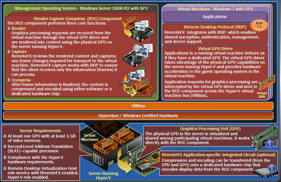
Hyper-V Architecture with RemoteFX Components (Windows Server 2008 R2 SP1 )
Microsoft RemoteFX™ is a LAN-based, server-side rendering graphics feature that delivers a rich user experience to virtual machines. It virtualizes and shares the graphics processing unit (GPU). RemoteFX is a new feature in Windows Server 2008 R2 Service Pack 1 (SP1).

Friday, February 11, 2011

Hyper-V Network Architecture

Virtual Network Architecture:

                       Hyper-V supports three types of virtual networks: private virtual networks, internal virtual networks, and external virtual networks. The virtual network switch forms the center of all Hyper-V virtual networks. It never appears as a physical entity—it is a software representation.

 
Virtual Network Interfaces in Hyper-V :

In Hyper-V, the virtual machine queue (VMQ) feature enables physical network adapters to use direct memory access (DMA) to place the contents of data packets directly into virtual machine memory, which increases I/O performance.

Data Path Without Virtual Machine Queue :

In standard Hyper-V environments, the virtual network switch in the management operating system filters data based upon MAC address and VLAN tags. It copies the data and then routes it to the associated virtual machines through the virtual machine bus (VMBus). Non-VMQ-enabled physical network adapters use the following device data path:

 
Data Path with Virtual Machine Queue:

With Hyper-V in Windows Server 2008 R2, you can use the VMQ-enabled network adapter to copy received data directly to a virtual machine’s accessible memory. This avoids the copy of received data from the management operating system to the virtual machine. The network adapter card must have hardware support for virtual network queue (VMQ).


Hyper-V Virtual Machine Snapshots

Virtual Machine Snapshots

Snapshots are read-only, ―point-in-time‖ images of a virtual machine. You can capture the configuration and state of a virtual machine at any point in time, and return the virtual machine to that state with minimal interruption. Multiple snapshots can be created, deleted, and applied to virtual machines. Snapshots form parent-child hierarchies with a parent virtual hard disk (VHD) and automatic virtual hard disks (AVHDs).

 
In Hyper-V Manager, when you create a snapshot the following occurs:
  1. The virtual machine pauses.
  2. An AVHD is created for the snapshot.
  3. The virtual machine is configured.
  4. The virtual machine is pointed to the newly created AVHD.
  5. The virtual machine resumes (the time lapsed is not perceivable by end user).
  6. While virtual machine is running, the contents of the virtual machine's memory are saved to disk. If a guest operating system attempts to modify memory that has not yet been copied, the write attempt is intercepted and copied to the original memory contents.
  7. When the snapshot is completed, the virtual machine configuration file, the virtual machine saved state files, and the snapshot (AVHD) are stored in a folder under the virtual machine's snapshot directory.
 
Snapshot Deletion:

Deleting a snapshot deletes all the saved state files (.bin and .vsv files). Hyper-V takes different actions on AVHDs, depending on the location of deleted snapshots relative to the running state of the virtual machine.
When you delete a snapshot, the following occurs:
  1. The copy of the virtual machine configuration taken during the snapshot process is removed.
  2. The copy of virtual machine memory taken during the snapshot process is removed.
  3. When the virtual machine is powered down, the contents of any "deleted" AVHDs are merged with its parent.
 
Deleting a snapshot subtree deletes the selected snapshot and any snapshots listed hierarchically underneath it.
  1. Deleting a snapshot between the first snapshot and the running state of the virtual machine preserves AVHDs. When the virtual machine is shut down, the data in the AVHDs is merged with the parent.
  2. If the deleted snapshot exists on a different branch or the same branch but at a point in time after the running state of the virtual machine, then the AVHD is deleted immediately.
 
Applying Virtual Machine Snapshots:

Applying a snapshot to a virtual machine basically means copying the complete virtual machine state from the selected snapshot to the active virtual machine. This effectively returns your current working state to the previous snapshot state. Any unsaved data in the currently active virtual machine will be lost if you do not take a new snapshot of the current virtual machine state before you apply the selected snapshot.
 

Thursday, February 10, 2011

Hyper-V Storage Types

Hyper-V Disk Storage Types :

                          For data storage, virtual machines use either a virtual hard disk (VHD) or a physical disk that is directly attached to a virtual machine (also known as a ―pass-through‖ disk). You can easily configure virtual machines to use either a fixed-sized VHD or a dynamically expanding VHD, or to directly access a physical disk. All virtual machines access virtual storage using virtual storage controllers, specifically a virtual IDE or SCSI controller.

Virtual Hard Disk Architecture:

                         A .vhd file is created on a host volume and exposed as a virtual hard disk to the virtual machines. The .vhd file functions as a set of disk blocks and is stored as a regular file using the NTFS file system. There are three types of VHDs: fixed-size, dynamically expanding, and differencing.

Storage Type: Fixed-size VHD
    1. A fixed-size VHD is a file stored in an NTFS partition that uses the full amount of space specified when the VHD was created.
    2. A fixed-sized VHD performs slightly better than a dynamically expanding VHD because the VHD file is initialized at its maximum size when it is created on a physical hard drive.
    3. You can always increase the size of a fixed-size VHD using Hyper-V Manager or by running a Windows PowerShell script.
    4. Maximum size of a fixed-size VHD = 2040 GB
Storage Type: Dynamically Expanding VHD
    1. A dynamically expanding VHD is a file stored on an NTFS partition that grows in size each time data is added. It provides an efficient use of available storage.
    2. You can compact a dynamically expanding VHD, which reduces the size of the .vhd file by removing unused space left behind when data is deleted from the VHD.
    3. Maximum size of a dynamically expanding VHD = 2040 GB
    4.  
Storage Type: Differencing VHD
    1. A differencing VHD is a special type of VHD that stores changes to an associated parent VHD for the purpose of keeping the parent VHD intact. Changes continue to accumulate in the differencing VHD until it is merged to the parent disk.
    2. The parent VHD of a differencing VHD can either be a fixed-size VHD, a dynamically expanding VHD, or a differencing VHD (differencing chain).
Storage Type: Physical Disk
    1. Disk storage can be configured as a physical disk directly attached to a virtual machine. In addition, disk storage can be configured as a storage area network (SAN) LUN attached to a virtual machine. These disks are also known as ―pass-through‖ disks.
    2. From the management operating system perspective, the disk is in an offline state, which means direct read and write access to the disk is not available.
    3. These disks do not support dynamically expanding VHD, differencing VHD, or virtual machine snapshots.
    4. These disks are not limited to 2040 GB in size.
 

Hyper-V Live Migration Operations

                   With live migration, you can move a running virtual machine from one physical server to another without interruption of service. Live migration requires the Failover Clustering feature to be added and configured on the servers running Hyper-V.

Hyper-V Live Migration Process:
  1. Create a network connection between computers for transferring virtual machine configuration data. Then create a virtual machine on the destination computer.
  2. Memory assigned to the migrating virtual machine is copied over the network to the destination computer. This memory is referred to as the working set of the migrating virtual machine.
  3. Duplicate remaining memory pages are transferred to the destination computer. The source computer also transfers the register and device state of the source computer.
  4. Control of the storage associated with the source computer, such as any VHD files or physical storage ―pass-through‖ disks, is transferred to the destination computer.
  5. The destination computer is now able to access virtual machine memory and storage. The new virtual machine is now active.
  6. The virtual machine is now migrated to the destination computer. The physical network switch is informed, and it refreshes its MAC address table so that network traffic now uses the correct switch port to communicate with the migrated virtual machine.

Windows Server 2008 R2 Cluster Shared Volumes (CSV):

                       Cluster Shared Volumes simplifies the configuration and management of clustered virtual machines. With CSV, multiple clustered virtual machines can use the same physical disk, while still being able to fail over (or move from node to node) independently of one another. In Windows Server 2008 R2, the Cluster Shared Volumes feature included in Failover Clustering is only supported for use with the Hyper-V server role.

                       It is necessary to have the operating system on the same drive letter on every node in the cluster to allow the virtual machines to access their files from each node.
CSV supports dynamically expanding, fixed-sized, and differencing virtual hard disks.

Coordinator Node:
Cluster Shared Volumes are volumes in a failover cluster that multiple nodes can read from and write to at the same time. The nodes coordinate the reading and writing activity so that the disk is not corrupted.

Only one node in the failover cluster owns the Cluster Shared Volume. That node is known as the coordinator node. There is only one coordinator node for each shared volume, and it is selected automatically.

Wednesday, February 9, 2011

Hyper-V Architecture

This poster provides a visual reference for understanding key technologies in Windows Server 2008 R2 Hyper-V.

How Installing the Hyper-V Role Changes Architecture:

                    You can install Hyper-V as a role in Windows Server 2008 R2. It installs all the components of the Hyper-V technology, including the remote management tools. Hyper-V introduces architectural changes to Windows Server 2008 R2. Hyper-V can be installed as a role on a Server Core installation of Windows Server 2008 R2 or as a role on a full installation of Windows Server 2008 R2.

Windows Server 2008 R2 Hyper-V Product Classification:

Windows Server 2008 R2 includes a hypervisor-based server virtualization technology that can be installed as a role in Windows Server 2008 R2.

Microsoft Hyper-V Server 2008 R2 is a stand-alone server virtualization product. It includes the Windows hypervisor, the Windows Server driver model, and virtualization components.
Windows Server 2008 R2 Detailed Hyper-V Architecture :

                     When the Hyper-V role is added to Windows Server 2008 R2, Windows hypervisor takes control of the physical computer and creates partitions. The parent partition becomes a special virtual machine that runs the management operating system (Windows Server 2008 R2), which you use to manage virtual machines. You can create virtual machines that run guest operating systems in the child partitions.